
Activity 1.1.3 Scientific and Engineering Notation
description:In electronics, we frequently work with very small and very large numbers. For example, the propagation delay (i.e., the time it takes for the output to change after the input has changed) for a standard digital logic gate is 0.0000000095 seconds. Moreover, the clock speed of a typical personal computer is 2400000000 Hz. Working with numbers of this magnitude, both large and small, can be cumbersome and prone to error. For this reason we use a power-of-ten notation. With a power-of-ten notation, any number, no matter how large or small, can be expressed as a decimal number multiplied by a power-of-ten.
Conclusion
1. Why is it important to use a power-of-ten notation (i.e., scientific or engineering) when expressing very large or very small numbers?
Because its easier to see and recognize how small or big the numbers are.
2. In engineering in general, and in electronics specifically, why do we use engineering notation rather than scientific notation?
Because we went to use the prefixes that are provided.
3. The SI prefix for 10-15 is femto and is abbreviated f. We do not use this prefix in electronics. Why? Because we use farad units (F) to avoid conflict between then we don’t use it.

Activity 1.1.7 Introduction to Datasheets
Introduction
Who fought in the Battle of Hastings in 1066? Who invented Silly Putty? Which of the Wright brothers flew first? All very important questions, but it would simply be impossible to keep all of the answers to such questions in your head. This is why we turn to the available resources like the Internet and textbooks to retrieve such information when necessary.
Conclusion
1. Using the datasheet obtained for the 74LS04 Hex Inverter Gates as a reference, answer the following questions:
What is the nominal Supply Voltage (Vcc)?
5
What is the maximum Free Air Operating Temperature (TA)?
70
What is the typical LOW-to-HIGH Propagation Delay (TPLH)?
3-10
What is the typical distance between two adjacent pins on a 14-Pin Dual-In-Line IC Package?
.007 inch
2. Who is Jack Kilby? What was his contribution to the field of digital electronics?
Jack Kilby was an American Electrical Engineer who invented the integrated circuit
3. In the purpose section, you were asked (i) Who fought in the Battle of Hastings in 1066, (ii) Who invented Silly Putty, and (iii) Which of the Wright brothers flew first.
We can’t leave these questions unanswered, can we? The answers are;
(i) England and France, (ii) James Wright, and (iii) Orville.
4. Likewise, in the purpose section, you were asked;
(i) What is the function of a MAN6760,
(ii) How many pins does an LM555 time have, and
(iii) What is the maximum supply voltage for a 74LS08.
Answer the questions below.
· MAN6760 Seven Segment Display
· LM555 ______8_______________
74LS08 _______5.25___________
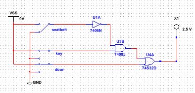
Activity 1.2.1 Introduction to Combinational Logic Design: Seat Belt Circuit
Introduction
Combinational and sequential logic are the fundamental building blocks of digital electronics. Combinational logic, which is sometimes referred to as "combinatorial logic”, is characterized by its output being a function of the current input value.
A variety of different logic gates can be used to implement combinational logic circuits. Many of these gates will be studied in future units of this course. In this introductory unit, we will limit our designs to AND, OR, and INVERTER gates for the sake of simplicity.
In this activity you will use the Circuit Design Software (CDS) to build and test your first combinational logic circuits.
Conclusion
1. Combinational logic circuits surround us everywhere in our daily lives. Identify 3-5 examples of circuits that contain combinational logic that you interact with almost daily. the buzzer for open doors on school buses.a fire extinguisher, & the backup buzzer on school buses.
2. In this activity we used switches for the circuit inputs and a probe for the circuit output. Though this works fine for testing purposes, it does not reflect the actual sensors and indicator used in real-world applications of combinational logic circuits. List three input and three output devices that could be used with real world applications of combinational logic. input: switch, button, pull level
output:buzzer, light bulb, or probe

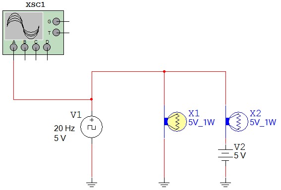
Activity 1.2.2 Analog and Digital Signals
Introduction
Even though this is a course in digital electronics, it is important to understand that the worldaround us is analog. Virtually everything that can be designed with digital electronics is usedto either control or monitor something in the world around us, and this world is analog. Thus,to be an effective designer of digital electronics, it is important for you to understand thecharacteristics of both analog and digital signals.
Conclusion
1. List the characteristic that makes a digital signal different from an analog signal.
An analog signal can have any value within a defined range.
A digital signal can only have specific discrete values.
2. In the diagram shown below, label the parts of the analog signal.
A – Amplitude (Peak to Peak)
B – Amplitude (Peak)
C – Period
3. In the diagram shown below, label the parts of the digital signal.
A – Amplitude
B – Time High (tH)
C – Period (T)
D – Time Low (tL)
E – Rising Edge
F – Falling Edge
4. What are the two standard voltage levels that are acceptable for a digital signal?
0V and 5V

ACTIVITY 2.1.2 Binary Number Systems
Introduction
Have you ever wondered why we use the base-ten, or decimal, number system? Of course, we have ten fingers. The decimal number system that works so well for us is completely incompatible with digital electronics. Digital electronics only understand two states, ON and OFF. This is why digital electronics use the base-two, or binary, number system. In order for you to be able to design digital electronics, you will need to be proficient at converting numbers between the decimal and binary number systems.
Conclusion
1. The decimal number system has served humans well since the beginning of mankind. Ug the caveman didn’t call it the decimal number system, but he undoubtedly used his fingers to count objects in his world. If the decimal system is so good, why do computer and other digital electronic devices use the binary number system?
The computers use the binary number system because it is impossible to create a digital circuit that operates in any base other than
· 011010 (2) - 26 (10)
4. How were you able to determine this?
I converted each of the binary numbers to decimal. I could have also looked at the MSB and if it was turned on, then that binary number would be the largest.
Introduction
Have you ever wondered why we use the base-ten, or decimal, number system? Of course, we have ten fingers. The decimal number system that works so well for us is completely incompatible with digital electronics. Digital electronics only understand two states, ON and OFF. This is why digital electronics use the base-two, or binary, number system. In order for you to be able to design digital electronics, you will need to be proficient at converting numbers between the decimal and binary number systems.
Conclusion
1. The decimal number system has served humans well since the beginning of mankind. Ug the caveman didn’t call it the decimal number system, but he undoubtedly used his fingers to count objects in his world. If the decimal system is so good, why do computer and other digital electronic devices use the binary number system?
The computers use the binary number system because it is impossible to create a digital circuit that operates in any base other than
- Now that we are using a number system other the decimal, it is important to properly subscript our numbers (i.e., 3510, 23410, 100102, etc.). Why is this so important? Provide at least three examples where neglecting to subscript numbers could lead to confusion. This is important because someone could have 1000 and think that it is 8 in binary. It's important as to not have any confusion between the two (as shown in the example above).
- Without performing the binary-to-decimal conversions, which of the following two binary numbers is the larger number :
· 011010 (2) - 26 (10)
4. How were you able to determine this?
I converted each of the binary numbers to decimal. I could have also looked at the MSB and if it was turned on, then that binary number would be the largest.
- Perform the binary-to-decimal conversions and check your answer. Were you correct? Yes, I was correct.
- Examine the table that you completed in the procedure portion of the activity. What do you notice about the LSB (least-significant-bit)? What do you notice about the middle bit? What do you notice about the MSB (most-significant-bit)? Do you observe a pattern here? The LSB is on every other time for odd numbers. The middle bit is on every two times and the MSB is on every 4 times. Yes, I observe a pattern and the pattern is that it goes just like the binary number system.
- Based on your observations above, complete the table shown below.


Activity 1.2.4 Introduction to Sequential Logic Design: Counters (DLB)
Introduction
Along with combinational logic, sequential logic is a fundamental building block of digital electronics. The output values of sequential logic depend not only on the current input values (i.e., combinational logic), but also on previous output values. Thus, sequential logic requires a clock signal to control sequencing and memory and to retain previous outputs.In this activity we will use the D flip-flop introduced in the previous lesson. We are limiting our use to this type of flip-flop in this introductory unit because of its simplicity and ease of use. The D flip-flop is just one of many different types of flip-flops that can be used to implement sequential logic circuits.
Conclusion
1. The 2-Bit and 4-Bit counters you explored in this activity are referred to as “divide by two” counters. Explain the relationship between each consecutive flip flop and the order in which they are laid out in the design from right to left that creates a binary count.
The frequency gets cut in half each time a flip-flop is added to the design.
If the outputs are arranged from lowest frequency to highest frequency from left to right, the outputs create a binary count.
With 4 flip-flips the count is 0 to 15 (00002 to 11112).
2. If you added a 5th bit, what would you guess is the highest number you could count to?
With 5 flip-flips the count is 0 to 31 (000002 to 111112).
16 + 8 + 4 + 2 + 1 = 3
3. Can you think of 3-5 everyday items/products that might have a counter incorporated in them?
Answers may vary.
Virtually all circuits in practical digital devices have a mixture of combinational and sequential logic.
Vending Machines
Security Alarms
Thermostats
Electronic Battleship
Anything requiring memory
Project 2.1.6 AOI Logic Design: Majority Vote
Introduction
The United States 2000 Presidential Election between George W. Bush (Republican) and Albert "Al" Gore (Democrat) will be best remembered for the controversy over who won Florida's 25 electoral votes, and ultimately, who won the presidency.
Introduction
The United States 2000 Presidential Election between George W. Bush (Republican) and Albert "Al" Gore (Democrat) will be best remembered for the controversy over who won Florida's 25 electoral votes, and ultimately, who won the presidency.
